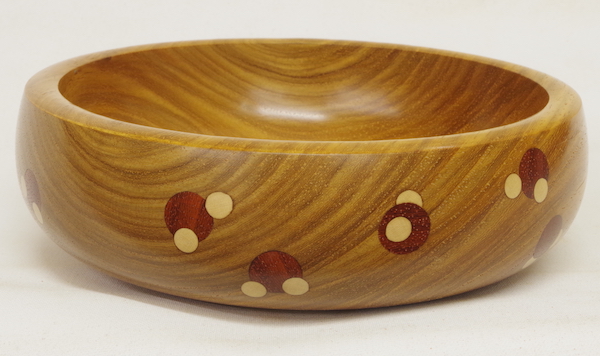
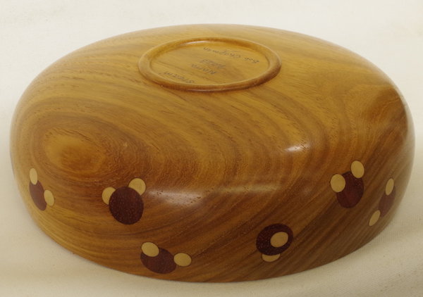
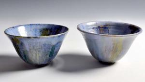
Bowl with molecular structures
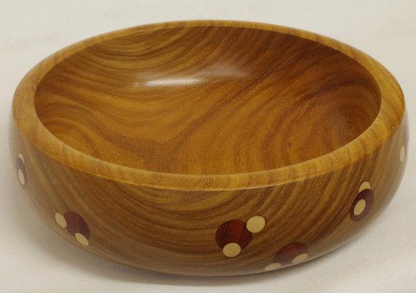
Some readers may know that I used to teach chemistry, and I’m always looking for ways to incorporate science into my turning. For some time now, I’ve been thinking of building models of molecular structures into a bowl.
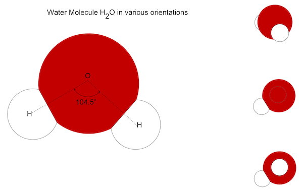
Fig.1 shows a representation of a water molecule. The oxygen atom is approximately twice the diameter of a hydrogen atom and there’s an international agreement about the colours used in molecular models – oxygen is always red and hydrogen white. This has an important bearing on the timbers chosen for the work (photo 1).
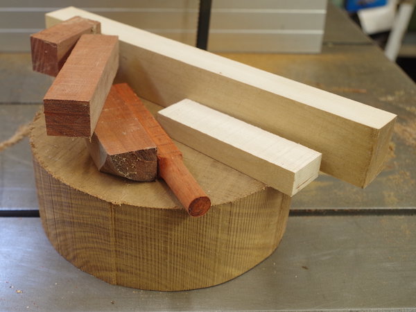
Timbers to represent colours
The reddest timber I know is padauk, which is the species chosen to represent oxygen. I have some holly, which is very white, and intended to use this for the hydrogen, but while searching the woodstore, I came across an even whiter piece of timber, which I wasn’t able to identify. It’s certainly not holly, but think it may be sycamore. Anyway, it seemed ideal for the task and that’s what I used.
For the bowl’s body, I wanted something that’d contrast with both of these, so ended up choosing a piece of Narra, which I’d been given years ago. A mid-brown colour with a distinct grain, although I’d never used Narra before, I found that it worked well. Although the dimensions are unimportant as any suitably sized piece of timber will do, mine was about 175mm diameter × 65mm thick.
Shaping the bowl’s exterior
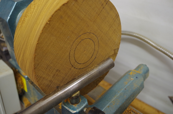
To start, I mounted the Narra blank on a screw held in the chuck jaws, then brought up the tailstock – mainly to mark a centre on the blank for use later on. Next, I marked two pencilled circles onto the blank (photo 2): the inner one shows the spigot’s diameter, which will be used when reversing the bowl. The size of this is governed by the chuck, which will be used to grip it. The outer circle matches the diameter of the bowl’s foot; this is about a third of the bowl’s diameter, which usually looks about right. I consider it a mistake to try and make the spigot double up as the bowl’s foot.
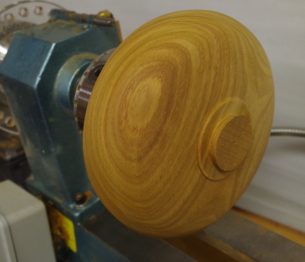
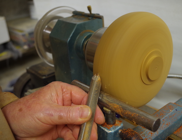
Using a combination of parting tool and skew chisel, I formed the spigot into a dovetail shape, which could be gripped securely in the chuck jaws, then proceeded to rough out the foot until it was around 3mm deep (photo 3). At the same time, I formed the bowl’s exterior shape using a 13mm bowl gouge, but at this point, made no attempt to give the bowl a fine finish.
Second time lucky
I used an imperial 1⁄2in Forstner bit for the oxygen atoms and a 1⁄4in one for the hydrogens – these provided the 2:1 ratio and looked about right on a test piece. At this point, I should confess that this is my second attempt at making the bowl... During the first go, I skimmed the bowl down after inserting all the ‘oxygen atoms’, then again after gluing in the ‘hydrogen atoms’. Having started to sand it all down, I soon found that I’d actually sanded away one of the hydrogens. ‘Oh crikey’, I said. After re-drilling and inserting another, I had to skim it again followed by more sanding – and promptly went through a second one! After about four or five such repairs, I gave up and started from scratch, but this time spent far more time thinking it through.
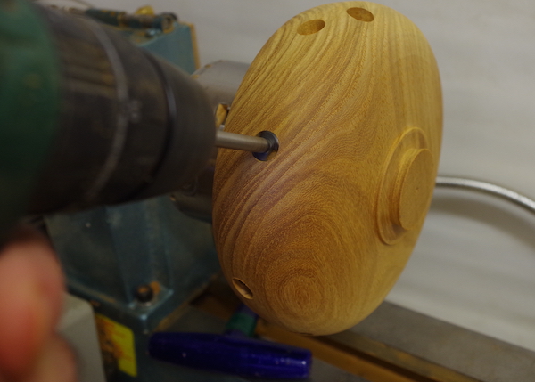
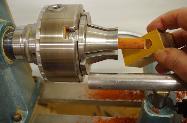
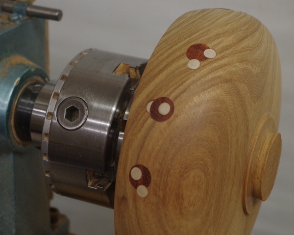
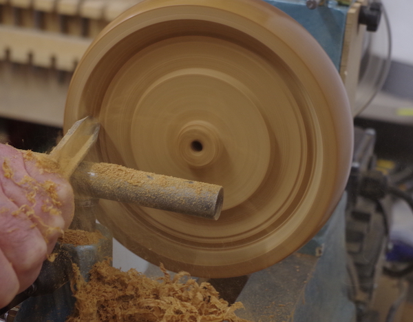
First time round, I’d deliberately drilled very shallow holes, which resulted in the inserted pieces having very little depth. With hindsight, however, I now drilled the holes approximately 6mm deep (photo 4), randomly around the bowl, then turned down a piece of padauk to fit, using a test hole in a piece of scrap to get the size right (photo 5).
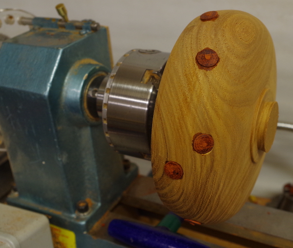
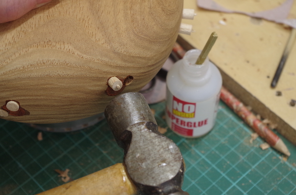
Next, I parted off short sections of this – approximately 8mm long – and glued them into the holes. As I’d actually bothered to measure the holes’ depths, I knew that each plug should bottom in the hole and leave a couple of millimetres standing proud (photo 6). I glued these in place with a drop of CA adhesive in each one.
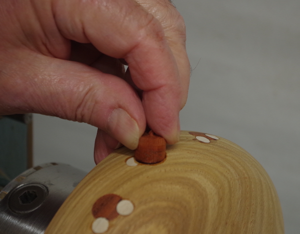
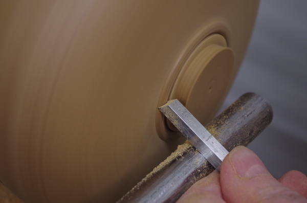
At this point, the bowl was skimmed to remove most of the excess padauk (photo 7) and the smaller holes drilled – 6mm deep as before – with two to each oxygen. I turned the white wood down to the required diameter – using the same method as for the padauk – and parted off 8mm lengths before gluing into the holes (photo 8).
Overlapping circles
This completed the first set of water molecules; however, what would be seen in reality – if any of the detail was even visible at all – would vary according to the viewing angle. For example, some molecules would seem to have only one hydrogen atom because the second one was out of sight and hidden behind it. Thus, I decided to use simple overlapping circles to represent the atoms in each molecule, but wanted some instances of the oxygen overlapping the hydrogen and vice-versa.
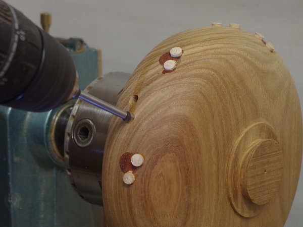
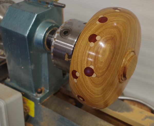
To achieve this, I drilled further small holes around the blank where there were no ‘oxygens’ (photo 9). When plugged with white timber, they can be overlapped with the larger holes ready to accept the red timber (photo 10). Once completed, the bowl exterior can be given its final skimming and sanded to a smooth finish, safe in the knowledge that the ‘molecules’ must still be at least 4-5mm deep and safe from being turned away completely (photo 11).
Bowl’s foot
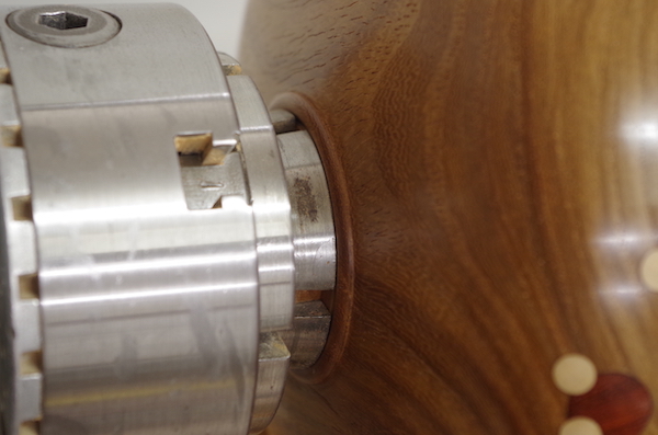
Before turning the blank round in order to hollow the bowl, I decided to smarten its foot using an Ashley Iles beading tool. This gives a neat 6mm bead (photo 12) on which the bowl will sit when the spigot is finally removed later on. The bowl’s underside could then be sanded from 120-400 grit and polished with Carnauba wax (photo 13). Next, I removed the blank from the screw chuck and reversed it so that the spigot was held in the chuck’s dovetail jaws.
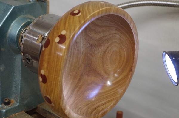
To prevent wobble, it’s essential to ensure that the blank is pushed securely up to the chuck jaws’ faces (photo 14). Using a 13mm bowl gouge, I began to gradually excavate the bowl’s interior. I now had a decision to make – should I leave the walls thick enough to cover the ‘molecules’ embedded within, or go thin enough to expose them on the inside?
Exposing them appealed to me but how thin would I have to go? If I damaged them now, I didn’t think a repair would work, so opted to carefully measure the wall thickness, leaving it around 8mm thick (photo 15). Now that it’s safely too late to change it, I do regret making that decision; it would’ve been more interesting to see them from both sides – oh well...
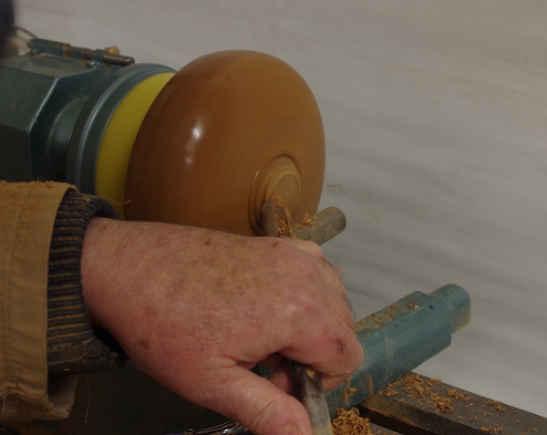
Negotiating the curve
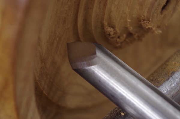
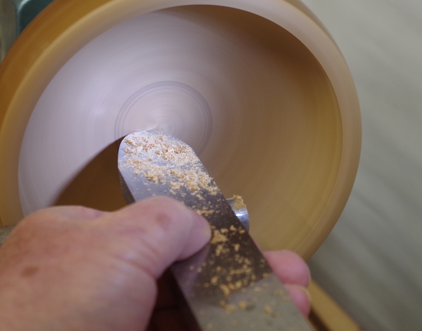
As hollowing progresses, quite a tight radius develops at the wall’s bottom and to get round this curve, a change of gouge is needed. The one shown in photo 16 has the back of the bevel ground away in a series of mini-bevels, which makes it much easier to negotiate the curve. Using a scraper, the bowl interior is finished with a series of very light cuts (photo 17).
Run your fingertips lightly over the bowl bottom to feel for high spots.If you find any, mark with a pencil before attempting to remove them. It’s very easy to take wood away from the wrong place and make matters worse – you may be able to see the pencil marks in photo 17. Sand through to 400 grit and polish the bowl’s interior (photo 18).
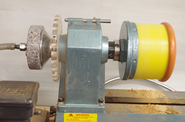
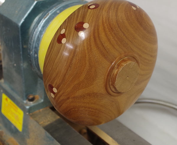
Vacuum chucking
The last task is to remove the spigot that’s held in the chuck. I do this using a homemade vacuum chucking system (photo 19). The bowl is placed over the chuck and centred by bringing the tailstock up to the centre mark made right at the beginning. With the vacuum pump switched on, the tailstock can now be removed (photo 20). The vacuum holds the bowl securely while the spigot is turned away, then sanded and polished (photo 21).
If you don’t have a vacuum system, however, you can mount a flat wooden plate in the chuck and use the tailstock to apply pressure. Turn down the spigot to leave a small stub where the tailstock is. Using a sharp knife or chisel, remove the stub, then finally sand and polish bowl surfaces by hand.
- Log in or register to post comments


| Articles | Articles | Articles | More | Subscriptions | Resources |