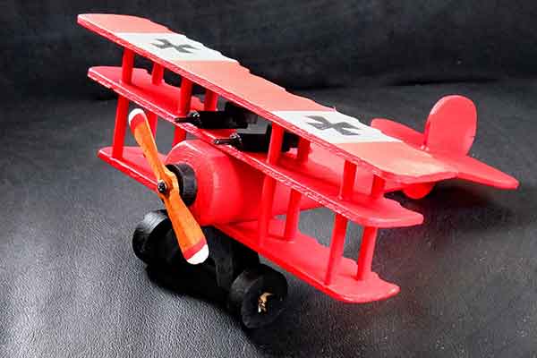
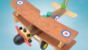
1917 Fokker DR-1 triplane toy
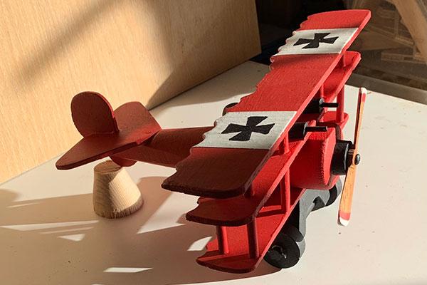
I’ve delighted in the early days of flying since childhood. I also love making things out of scrap, so when my Goddaughter’s son – four-year-old Finley – wanted a toy plane for Christmas, I delved into the odds and ends box thinking a Fokker Dr-1 ‘Red Baron’ triplane would be perfect for him, not to mention a lot of fun for me.
I used some 4mm ply, which was left over from an old cabinet; a piece of spare beech worktop; some 50 × 50mm sawn timber from a skip; and – although I had to buy these – a few lengths of dowel plus tubes of red, white and black acrylic paint. As I was making this for a very bright child, it therefore needed to be reasonably accurate, so I used a free online plan.
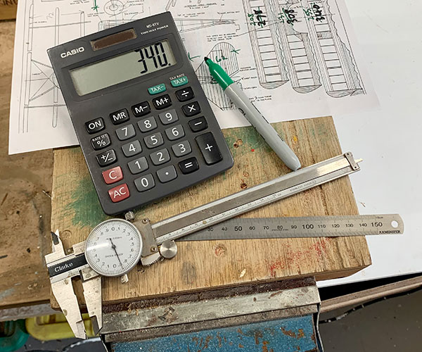
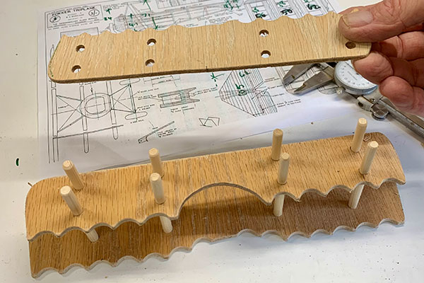
The plan gave no dimensions and was slightly too small, so I began by measuring everything and multiplying by 1.5 (photo 1). If you search online, you’ll discover dozens of Fokker triplane plans – I found mine on Pinterest and it was free to download and use. Have a look for yourself and find a version you like, then play around with the dimensions to suit.
Making the wings
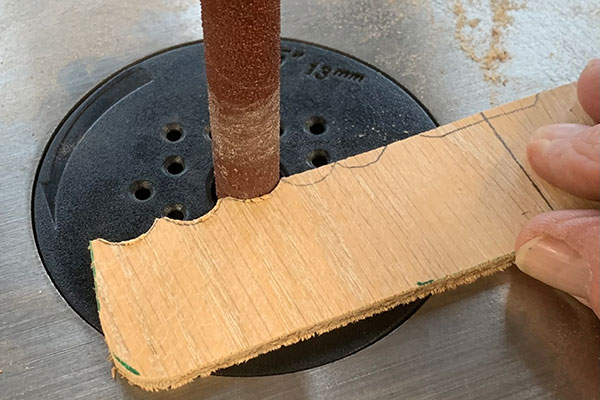
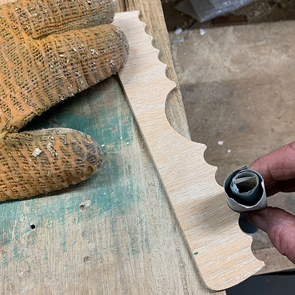
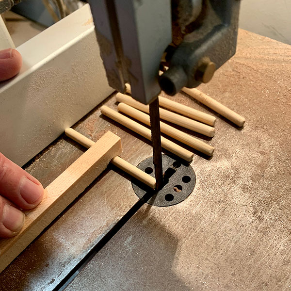
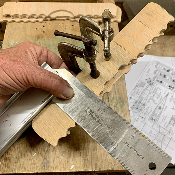
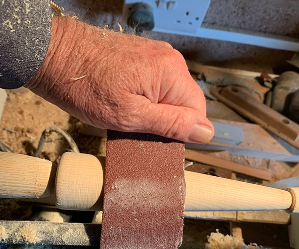
The Fokker’s wings have a complicated detail – beautifully scalloped rear edges – but marking out is simple, and a bobbin sander is perfect for helping to achieve this (photo 2). Next, twirl a sheet of 400 grit abrasive into a roll and begin to sand the detail (photo 3). The eight struts are constructed from simple, 5mm dowelling – available from any DIY store – but they must all be the same length. An easy setup for achieving this is a bench-top bandsaw and guide (photo 4) – ensure to use a push stick here.
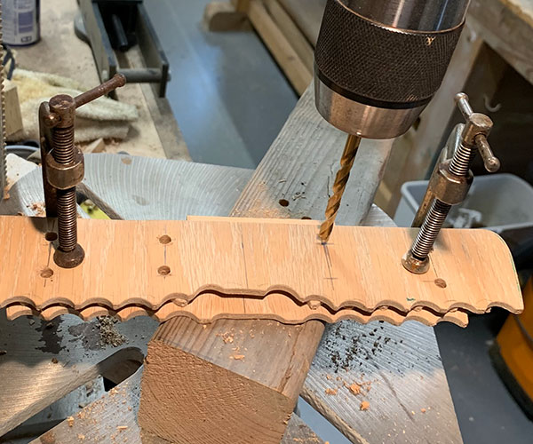
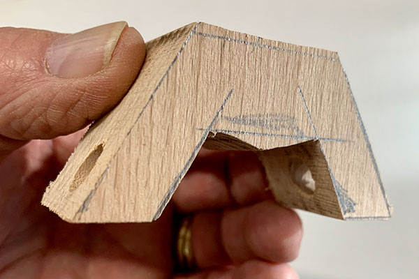
The three wings are different lengths, and interestingly, the Fokker’s success was partly due to additional lift from its ‘extra’ wing, despite the added drag. Early designers were doubtless tormented by the power/weight/lift/drag formula – one that clearly worked well on the Fokker – and it could reach 110mph and climb to 15,000ft. This was quite an astonishing performance for 1917 – barely a decade after the Wright Brothers’ first flight. Before the wings are drilled to take the struts, they need to be carefully lined up. Mark a centreline on each, lay them exactly one above the other, slightly staggered so the upper wing is ahead by a few millimetres. Next, clamp them in place hen mark the hole positions – by eye to judge how far apart they should be – using a square to guarantee alignment (photo 5).
I’d recommend a bench drill for the next stage, or very careful hand drilling. The holes need to be vertical (photo 6) so that the struts line up easily. Use a 5.5mm drill for the holes; this will make fitting everything much easier. The stated diameter of dowelling is often incorrect – plus or minus 0.5mm is common – but check before drilling.
Tailplane unit
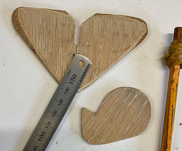
The same ply is required for these two pieces – a triangular horizontal stabiliser and small vertical fin and skid (photo 7). The horizontal part will sit on the flat at the end of the fuselage. Ensure to take care when gluing later, as this part must be parallel to the main wings. The fin and skid will sit in the slot you’ll mark out shortly.
Assembling the tri-wing unit
To assemble, lay the bottom wing flat on the bench, top uppermost, and apply a drop of glue into the holes. Push a strut into each hole, then slide the middle wing down the struts (photo 8). Don’t glue the middle wing just yet – instead, push it down and apply a dab of glue to the ends and top 3mm of each strut. Now push the top wing over all eight struts until these are level with the surface. This is a bit fiddly, but you’ll be glad you shaped a chamfer and kept the wings the correct way up – even more obviously – with the scalloped edges facing the rear. Use a slow acting glue here – regular PVA is perfect.
You should now have three wings, which are held together by eight struts. Note: the middle wing isn’t glued – rather it’s loose on the struts and will be glued later. Now – while the glue is wet – make any small adjustments until all looks good, and leave the wing assembly on a flat surface for a few hours until the glue sets.
Fuselage & undercarriage
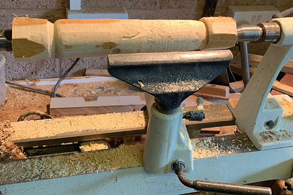
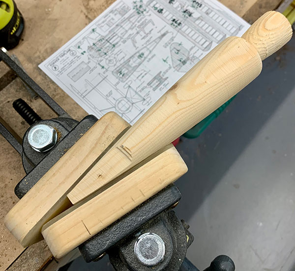
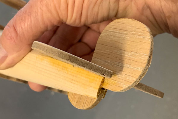
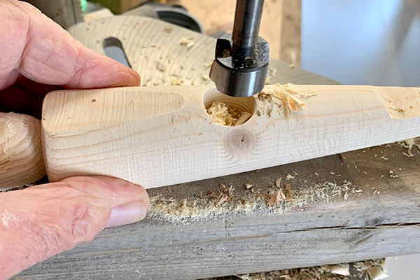
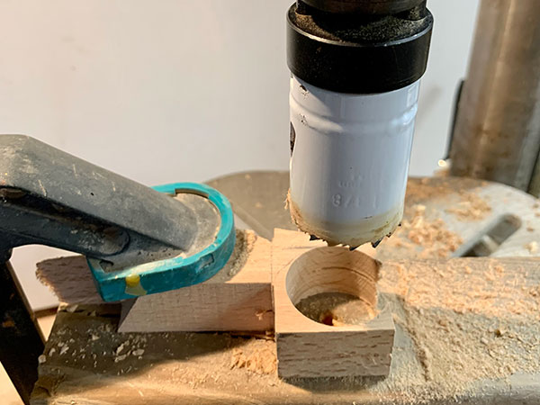
The fuselage is 40mm diameter at its widest and a simple job to turn and sand from 50 × 50mm stock on a small lathe (photos 9 & 10). If preferred, you can shape by hand, but either way, it needs to be finished by filing small flats where the wide front section touches the middle and lower wings. Further sanding – using a belt or disc sander – will flatten the very front. Shape the tail area almost to a point before filing another flat, this one for the triangular stabiliser (photo 11). If you’re using 4mm ply, mark two lines 4mm apart along this flat area (photo 12) and cut out using a fine saw. This slot will accept the fin and tail skid (photo 13). Finally, cut a hole for the pilot, ideally using an 18mm Forstner bit (photo 14). The pilot can be turned from a piece of scrap, or shaped using a bit of dowel, and glued in position later.
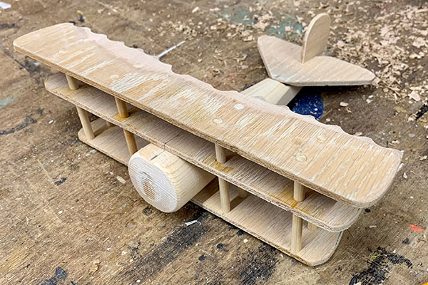
Once the wing assembly is solid, use a belt sander to sand the strut ends on the upper and lower wings and slide the fuselage into its final position between lower and middle wings – this is why you didn’t glue the middle wing in place. Line everything up so it’s parallel and square, and fix the middle wing in position with dabs of glue on the struts and fuselage (photo 15).
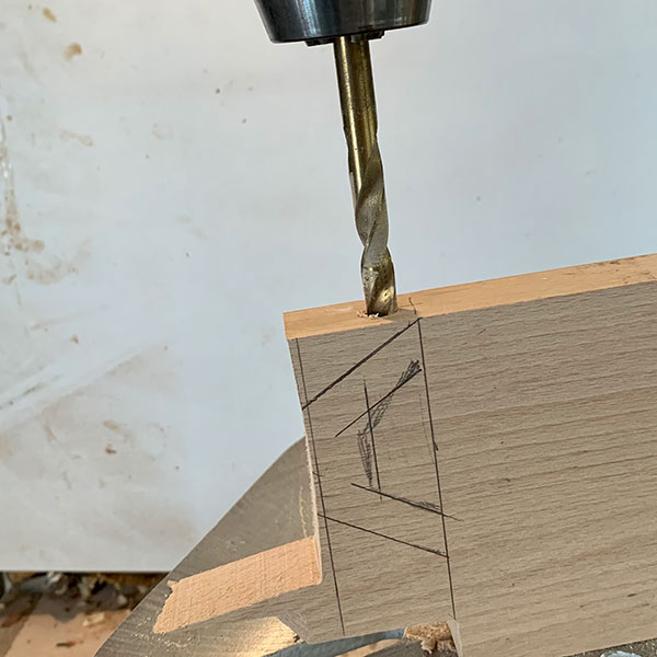
Most drawings – and of course the real plane – will have a delicate looking metal undercarriage, but something stronger is required here. Mark a piece of hardwood, but drill while it has a 90° end (photo 16), shape after it’s been sawn (photo 17) and drill a countersunk hole for a small screw; this will fix it to the bottom wing later. 8mm dowel is required for the axle and the wheels can be cut from hardwood scrap with an 8.5mm hole (photo 18), which will allow them to turn freely. A couple of wire pins will hold these in place.
Propellor & guns
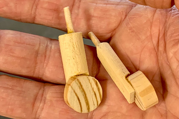
These tiny details add some realism, so it’s worth taking your time over them. Mark out the propellor so it’s 85mm long and drill the centre hole before shaping it. Put a dab or two of paint on the ends and fix in place with a small pan head screw. The DR-1 was well armed, carrying two 7.92mm Spandau machine guns; these are easily mocked-up from a few pieces of dowel (photo 19). In a superb technical achievement, some Fokkers had guns that were mechanically synchronised to fire through the arc of a spinning propeller!
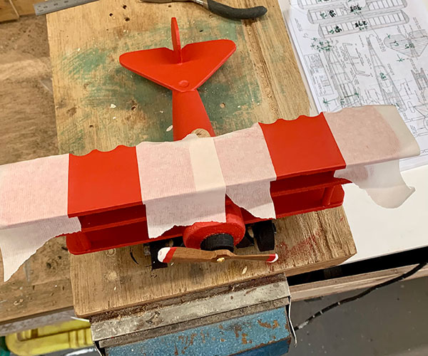
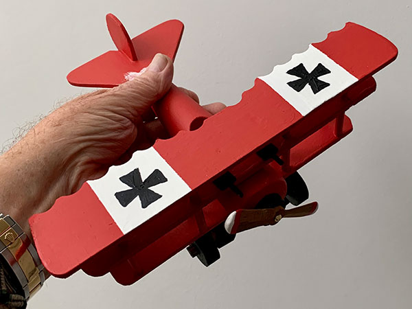
Painting & final assembly
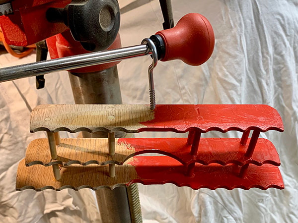
It’s easier to paint one end of the wings at a time, and swap ends once the paint has dried (photo 20). Later, mask up for the white areas (photo 21) ready to receive the black cross decoration (photo 22). Decals are available, but I enjoyed painting this detail by hand. When the undercarriage is dry, screw it to the fuselage through the lower wing, slide in the axle, then finally add the wheels and pins. The toy plane can then enjoy its first flight!
- Log in or register to post comments


| Articles | Articles | Articles | More | Subscriptions | Resources |