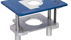
Jigs for bench top palm routing
In terms of their functionality I’m a fan of router tables. What I’m not so keen on is having to adjust the router when it’s upside down and in a confined space. I also prefer using routers on the bench top where possible because there’s a feeling of being in touch with the work and therefore a greater sense of control.
After spending some time at the workbench and sketching out ideas on paper it seemed plausible that this new palm router could be used with a bench top jig set-up that would allow certain types of work to be done on the bench top that is normally reserved for the router table.
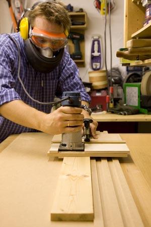
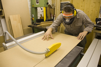
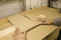
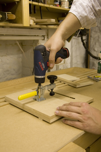
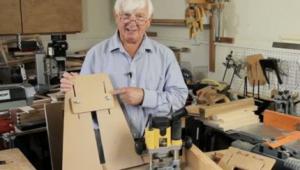
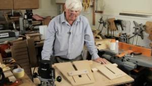
The housing and grooving jigs in use.
The design I’ve come up with uses a common base board with a front lip that sits on top of a workbench. The lip sits over the bench front and is fastened in place with a bench vice.
There are two jig designs outlined below that work with the base board; a housing jig and a grooving jig. The housing jig allows you to cut housings across wide boards for items like shelf units and other assemblies where ninety degree housing joints are required. This is a job normally reserved for mitre saws with a depth set and pull facilities or radial arm type saws. Routers are often used to cut housing joints too, but without a specialist jig such as this it can take some time to set up each housing cut. When using the jig outlined here housing joints become quick and easy to cut.
The grooving jig works on the same principle as the housing jig in that it relies on the bench mounted base board to function. It also has a similar, albeit more complex construction. Grooving is a job normally undertaken on a router table, or precariously with a fence! I found it a refreshing change to have a jig that allows me to groove accurately on the bench top.
| ITEM | LENGTH | WIDTH | THICKNESS | No. OFF |
| A: Base board | 1460 | 460 | 6 | 1 |
| B: Ribs | 1460 | 20 | 6 | 4 |
| C: End stop | 360 | 20 | 6 | 1 |
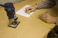
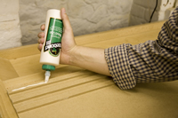
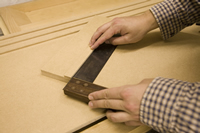
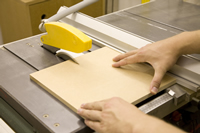
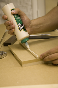
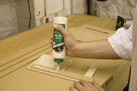
Measuring, cutting and gluing up the base board components.
Once you’ve cut all the components for the base board, assembling them is a quick and easy job. Simple rub joints are ideal and I opted to use them wherever possible for speed.
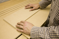
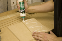
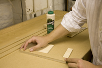
Apply a thin line of good quality wood glue to one side of three of the four ribs (B). Use the fourth rib (without glue applied) as a spacer to place the three ribs at equal distances from each other, starting at the rear bench side of the base board. Rub the ribs back and forth when in approximate position to create the necessary vacuum that makes for a good rub joint. If this is done correctly no clamping is necessary for a good flush joint. When the three ribs are in position double check that all edges are flush because due to the lack of clamps, rub joints do have a tendency to move easily. Leave the glue to set for an hour then continue with the next stage.
The fourth rib which was used as a spacer in the last step now forms the front lip that will align the base board with the front of your bench. Turn the base board over and rub joint the remaining rib to the front edge of the base board. Leave enough time for the glue to dry then turn the base board back over.
The last job to do is rub joint the end stop (C) into position. The end stop provides a stopping piece to hold timber in position securely when using the grooving jig. Now that the base board is made up we can make the housing and grooving jigs to accompany it.
| ITEM | LENGTH | WIDTH | THICKNESS | No. OFF |
| D: Housing base | 460 | 360 | 6 | 1 |
| E: Edge fence | 460 | 200 | 12 | 1 |
| F: Underside fence | 360 | 20 | 6 | 1 |
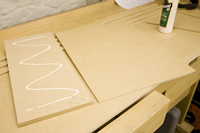
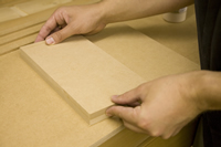
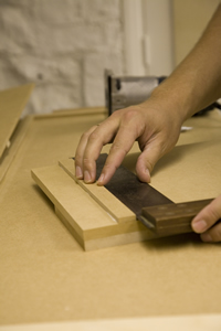
Applying glue, creating a rub joint and checking alignment of the components.
When the glue is set, turn the jig over and place the underside fence (F) in position. Set this in from the housing base edge by the width of the router base. Rub joint this in place and check for squareness with a good long square.
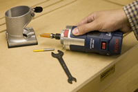
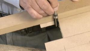
Fit your largest flute cutter.
Now the jig is almost complete. All we need to do is cut a through slot in the jig which will allow the router to run freely along the edge fence when routing housings. Fit your largest flute cutter to the router and proceed to cut a slot through the housing base while using the edge fence as a guide for the router. Start the groove with the centre of the cutter aligned with the inner most edge of the underside fence (so it doesn’t cut through the underside fence). There is no need to take the slot further because the underside fence marks the start point for any housing that will be cut. End the slot at approximately the same distance from the edge of the adjacent side. While cutting the slot make sure the cutter is just protruding through the housing base and doesn’t cut any unwanted grooves into the base board!
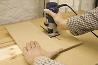
As soon as the slot is cut the jig is ready for use. Rest a squared up piece of timber against the rear fence of the base board then place the housing jig on top. The slot allows you to see any markings and line up the router.
When cutting the housing, support the jig with your left hand while guiding the router with your right hand. You’ll find creating housing joints is now easy, with very little set-up needed!
| ITEM | LENGTH | WIDTH | THICKNESS | No. OFF |
| G: Grooving base | 290 | 290 | 12 | 1 |
| H: Edge fence | 290 | 145 | 12 | 1 |
| I: Underside fence | 290 | 20 | 6 | 1 |
| J: Router housing (birch ply) | 290 | 145 | 9 | 1 |
| K: Clamp ridge | 290 | 30 | 6 | 1 |
Cut the components as accurately as possible with a table saw. The first steps when making the grooving jig are very similar to those of the housing jig. Rub joint the edge fence (H) to the grooving base (G).
Now accurately mark out the position of the underside fence. As before, inset the fence on the jigs underside so its furthest edge is the same measurement as the width of the router base.
Now rub joint the underside fence into position and check for accuracy with a square.
Applying glue and creating a rub joint.
From here on in the two jigs become quite different. What we need to do now is create an extended base plate for the router. This is listed on the cutting list as a router housing (J) and is made from 9mm birch plywood. I’ve opted for plywood for this component because it’s hard wearing and has good cross-grain strength. The router housing will be a key element to the functionality of the jig and needs to be tough.
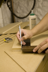
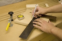
Marking out the underside fence position, applying glue and checking alignment.
The next step is to line up the router housing with the front of the jig and side of the edge fence, then mark the position of the router base plate onto the plywood for cutting out. If you can, cut this with a bandsaw for nice vertical cuts and keep the cut out very tight. You can always trim a little more material off later if needed. When marking the routers base plate, position the router cutters centre point so that it’s aligned with the furthest edge of the underside fence. The material left to one side of the cutout should be 30mm wide. Don’t worry about excess material on the adjacent side, having an open side makes for easier cutting and insertion of the routers base plate later on.
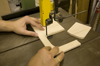
Using a bandsaw to cut out the
router base profile.
Fit the routers base plate into the cutout; it should be a nice tight fit. If it’s too tight, sand the edges back by hand with some 120 grit paper until it’s just right.
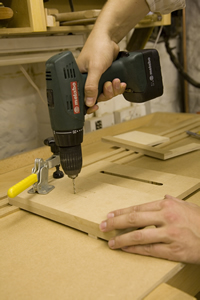
The next job is to cut a slot in the grooving jig. Because the centre of the cutter was lined up with the furthest edge of the underside fence when marking out the base plate cutout, you can start the slot cut where the router housing is flush with the front edge of the jig. Mark this distance with a pencil, measure and transfer it to the adjacent edge to mark the slot stop line. As before, fit your largest flute cutter and cut the slot between the start and end points. Again, be sure that the cutter has adequate clearance beneath the jig to avoid any unwanted grooves!
Now take the clamp ridge (K) and rub joint it to the edge of the router housing (J). When glued together and placed on the jig the clamp ridge should be 3mm higher than the edge fence. This is ideal and will form our clamping surface to hold the router in position when grooving.
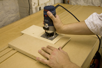
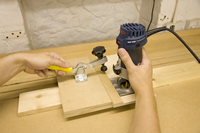
Routing the clearance groove and fixing the clamp ridge in place.
Now mark out a central position on the edge fence for the toggle clamp. The clamping head should be aligned with the centre line of the clamp ridge for secure clamping force when in use.
Marking the toggle clamp position.
When the toggle clamp is fixed the router housing can be clamped in any position along its length. This makes for very quick adjustment when using the router to groove or rebate a work-piece.
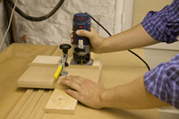
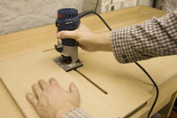
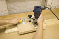
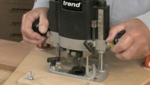
Now the jig is ready for use. Use the toggle clamp to position the router where you want the groove to be cut, place the jig over your work-piece on the base board and get grooving!
Fixing the toggle clamp in position.
By creating the base board and using it as a fence for the router jigs to work with, we’ve created a flexible bench top routing system that can be quickly set up and used with ease.
There are probably more jig designs that could work well with this base board design, so I guess it’s back to the sketch book to see what else will work ~ happy routing...
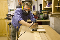
Using the toggle clamp to lock the router in position then using the router to cut a groove along the length of a piece of timber.
- Log in or register to post comments


| Articles | Articles | Articles | More | Subscriptions | Resources |