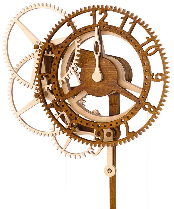
Rotara clock
This straightforward clock is designed as an entry-level device, which can be made by anyone with the time and care to spare; you don’t have to be a full-time clockmaker to complete it! Through its simple yet thoughtful design, anyone with a scrollsaw and steady hand can build the clock if they cut the parts carefully and exercise sufficient patience during construction.
Minimal movement
The number of moving parts has been reduced to only the essentials, and as there’s no minute hand, the clock doesn’t need a complex dial train. By having the hour hand fixed, it’s only necessary for the dial to rotate to display the current time; this operating motion gave the clock its name – Rotara. It’s easy to read the time from Rotara’s face, and you can mark additional quarter hour indicator holes on the hour wheel for improved time-telling accuracy.
Maximum efficiency
Optimised tooth geometry – the size and shape of the gear toothing for smooth running – the carefully calculated frame design and an improved pendulum suspension system all simplify the making of the clock considerably, as well as enhancing its operational performance.The drive weight is attached to a cord, which is wound around the winding barrel. To wind the clock, you simply move the counterweight downwards. It couldn’t be any faster and easier. This will give a running time of around 25 hours.
CNC router
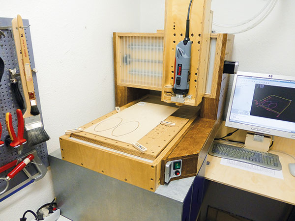
I made all the parts for Rotara using my CNC router (photo 1). Having been interested in making automata and similar devices for some time, I’ve developed my own homemade CNC machine to make the cutting-out work simpler and more accurate – it’s called Solidis. Scrollsaw enthusiasts will have no problem cutting out the components, and even a hand fretsaw will get the job done if used with care.
The right materials
For making the clock, I recommend using Baltic birch plywood, which is the best plywood available. This material is preferable due to its dimensional consistency and relative resistance to humidity and movement. Far-eastern and poplar plywood should be avoided owing to its poor quality and general unreliability.
The work is made a lot easier if you stick the paper plans to your plywood with a craft glue or aerosol spray adhesive. This leaves no residue when removed from the wood, and ensures you achieve a greater degree of accuracy with the project. To remove the paper from the wood, I’ve found it’s sometimes necessary to heat it a little using a hot air blower.
Making the frame
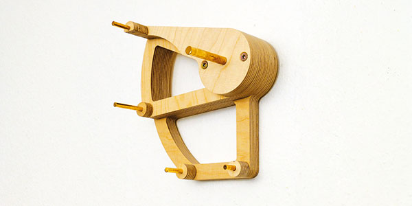
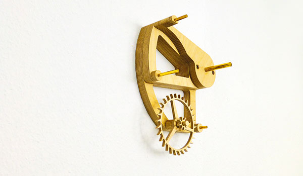
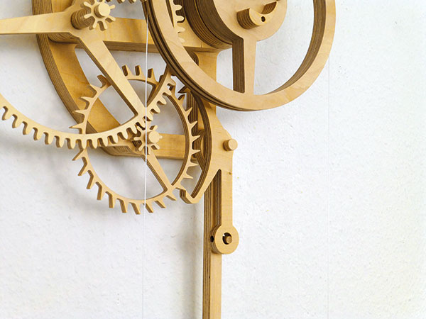
The frame is the baseplate onto which all other parts are attached (photo 2). Rotara uses a so-called single frame, which is very simple because tolerances during the cutting process aren’t as tight as they would be on a multiple-frame device. The axles – or arbors – are made from brass rod; this is normally available in the correct dimensions at your local hardware store or DIY shed. You only have to cut them to the correct length. The frame is attached to the wall with two screws, which aren’t visible.
Perfectly round
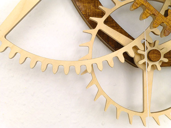
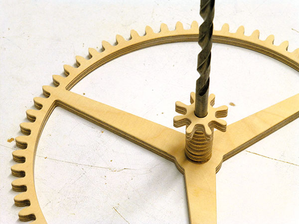
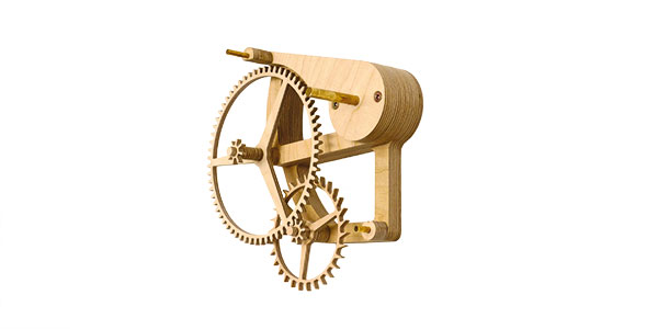
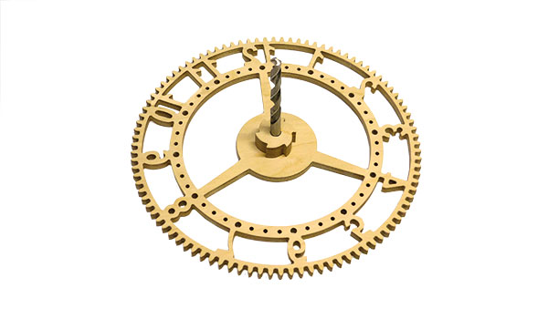
The escape wheel (photo 3) is the most important part of the clock. It must be a perfect circle to obtain a uniform ticking motion, but don’t worry; this can be readily achieved using a bench-top disc sander. Just take a piece of scrap wood and position the wheel on it so that it overhangs slightly. By using a close-fitting drill bit as a temporary centre, the scrap timber can be clamped to the sander table and the wheel slowly rotated against the disc until it’s perfectly round. Once finished, the escape wheel is the first component that can be fixed to the frame (photo 4).
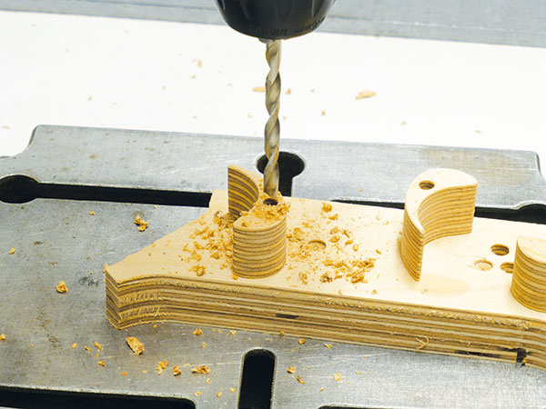
Getting into gear
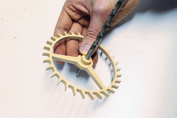
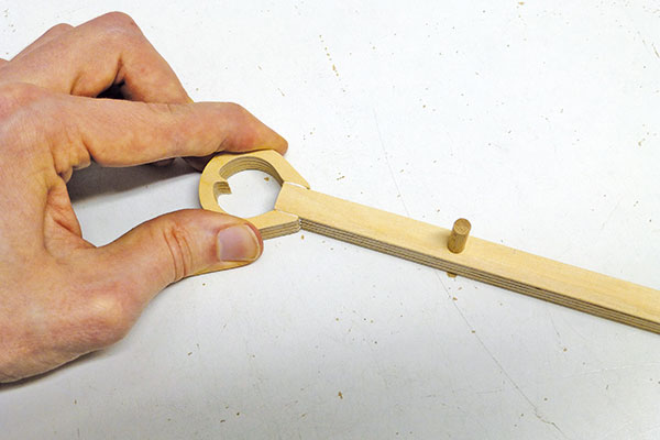
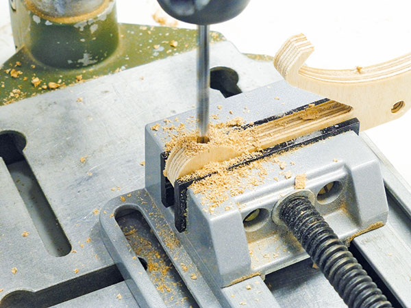
Cutting the gears isn’t as difficult as most people think. If you use spiral blades for your scrollsaw, you can cut the teeth with extreme precision. All of the small parts should be drilled before cutting out, because at this point they can be held more securely. To align the holes of the gear, the small pinion and spacer, you can again use a drill bit (photo 5). These parts can then be added to the frame (photo 6).
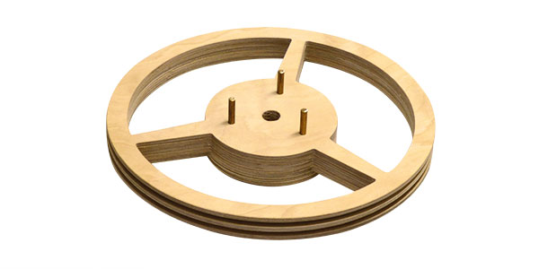
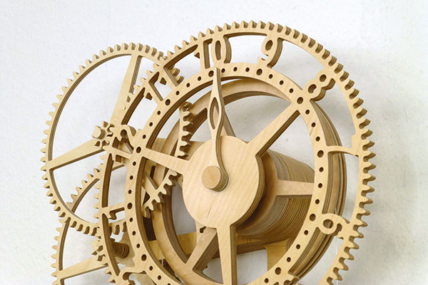
Over a barrel
The winding barrel, as its name suggests, is where the cord is wound up, and from which the weight is suspended. It’s designed as a sandwich wheel, consisting of several layers. You need to drill three holes for the pins of the ratchet mechanism into the face of this wheel (photo 7). The three ratchets (photo 8) ensure that the weight is firmly connected to the going train. If you wind up the clock, the ratchet releases the connection and you can then pull the weight without moving the other gears. Fit these in place on the frame (photo 9).
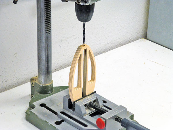
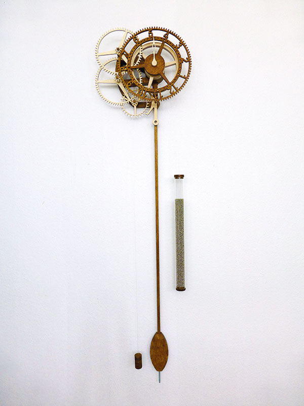
A swinging time
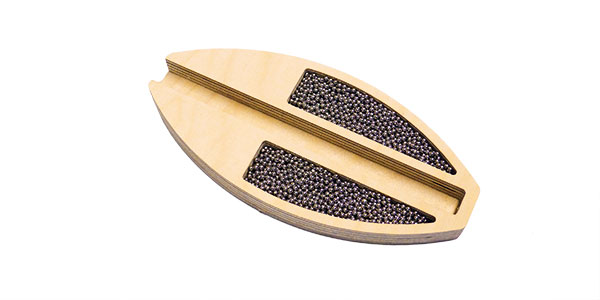
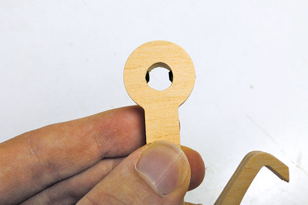
The pendulum regulates the time impulses of the clock. My construction of the bob also employs a sandwich technique. Drill a hole in the end of the central section after cutting to shape (photo 10). The middle part of the sandwich is hollow so that lead shot can be poured into it (photo 11). These very small lead balls are available from diving and sailing suppliers, who sell them to make up ballast bags and the like.
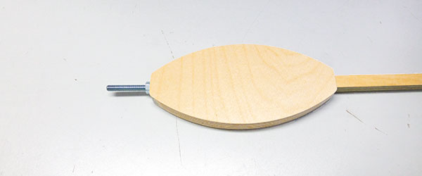
The pendulum also needs to be adjustable, so I’ve included a threaded rod at the bottom for calibration. It’s important to get the centre of gravity as low as possible. The threaded rod is screwed into the bottom of the pendulum shaft, which is then fitted into the pendulum bob (photo 12).
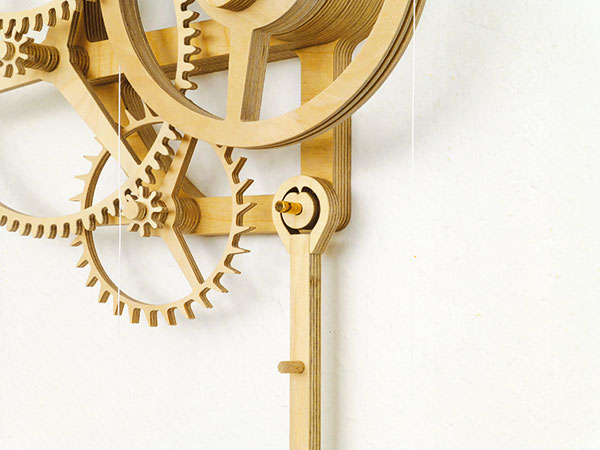
You’ll note that the top of the pendulum shaft terminates in a special head, which is the last piece of the pendulum to be fitted. This incorporates a V-shaped pin, which reduces the friction of the pendulum as it swings (photo 13). The finished pendulum can now be fitted to the frame (photo 14).
A vital link
The anchor connects the pendulum with the escape wheel, and is consequently a very important part of the mechanism (photo 15). To calibrate the anchor easily, two small grub screws are set into the end, which attaches to the pendulum (photo 16). A tap – and die – can be used to make the threads, or you can simply drive the screws directly into a pilot hole. With the anchor fitted (photo 17), you’re another step closer to completion.
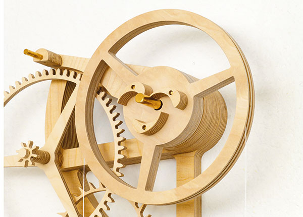
Telling the time
As this clock has a fixed hour hand, the dial has to rotate twice every day. That’s the reason the dial is also known as the hour wheel. The ratchet wheel is fixed to the back of the hour wheel (photo 18) and glued in place after using a drill bit to align the two holes. The hour wheel can now be fitted to the clock, followed by the hour hand, which is fixed in place and allows the dial to rotate behind it (photo 19).
Carry that weight
Rotara needs two weights to function fully (photo 20). The bigger one is the drive weight; this exerts a constant gravity-aided force on the winding barrel, which is transferred to the going train and drives the whole mechanism. I’ve made the drive weight from acrylic tube so you can see the lead balls, but you could make it in any shape or material you prefer. The small one acts as a counterweight and ensures that the winding barrel winds up the loose end of the cord cleanly, without tangling.
The clock is now complete, but you may wish to apply a finish. Contrasting stains are always a good idea, and can highlight the various components. Paint is an alternative, but it should only be applied very sparingly. Aerosol paint is a possible option as it’ll avoid clogging up the workings and undoing all your hard work!
Further information
See a video of the clock being made on my YouTube channel. Available in English and German, plans can be purchased via my website . These consist of building instructions, a materials list with reference sources, assembly and part drawings. You can print most parts at full-size for ease of cutting. If you’d like to make the parts using a CNC machine, I can email you the digital .dxf file.
- Log in or register to post comments


| Articles | Articles | Articles | More | Subscriptions | Resources |